DISCOVER OUR
PACKAGE OFFER
Complete rotary kiln monitoring by combining Kilnscan & Pyroscan
INDUSTRIAL THERMOGRAPHY FOR ENHANCED THERMAL PROCESS MONITORING
HGH is one of the world leaders in high value-added Industrial Thermography. Discover how HGH Industrial Thermography expertise help customers to control their industrial process, maintain equipment efficiency and reduce costs. As an infrared specialist for over four decades, HGH develops and manufactures rotary kiln scanners and cameras that are operated in hundreds of industrial sites worldwide.
About Industrial Thermography
Industrial thermography is a game-changing technology that enables enhanced thermal process monitoring across various industries. By providing real-time thermal insights, thermography helps detect early signs of faults, improve energy efficiency, ensure operational safety, and reduce maintenance costs. Investing in infrared thermography can significantly improve the reliability and longevity of critical equipment, ensuring smooth and efficient industrial operations.

Industrial Thermography Markets
Industrial thermography plays a pivotal role in various sectors, including manufacturing of cement, lime and minerals, and steel, but also industrial and household waste processing. Its ability to detect hidden thermal anomalies in inaccessible areas makes it an indispensable tool for modern industrial operations. Assessing temperature uniformity in ovens, furnaces, and heat exchangers to optimize processing conditions and prevent overloading avoiding cycle shutdowns and stressful restarts of furnaces.
Technical Expertise
Since more than 40 years, HGH specializes in thermal scanners and cameras for remote temperature measurements on rotary kilns, boilers and other high temperature processes. HGH temperature control solutions extend key equipment lifetime and enable preventive maintenance actions before irreversible damage occurs.
Improved reliability of Pyro-process with non-contact temperature measurement
Investing in high-resolution infrared cameras that provide clear, accurate thermal images is a paramount.
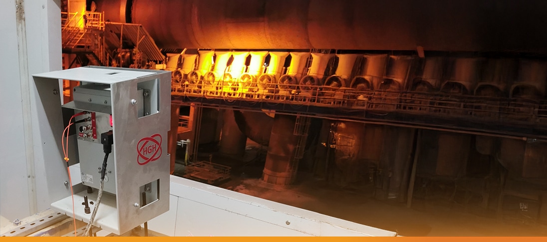
HGH offers innovative solutions specifically designed for kiln applications: KILNSCAN and PYROSCAN. These systems revolutionize kiln monitoring by providing detailed thermal analysis and real-time imaging. Pyrometric cameras allow the control of the flame shape for the optimization of material burning efficiency. HGH kiln scanners contribute to improving productivity and reducing unplanned shutdowns.
INNOVATION AT HGH
HGH industrial thermography uses infrared cameras to detect infrared radiation emitted from objects. The camera then converts this radiation into a thermal image, which shows temperature distribution. Hotter areas appear brighter, while cooler areas are displayed as darker regions. This visual representation enables operators to quickly spot thermal anomalies.


