

NIGHT VISION DEVICE (NVD) TESTINGAccording to MIL Standards
Key testing procedures for NVDs
Focusing and Resolution Measurement
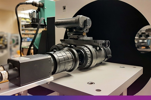
Adjusting the focusing and measuring the spatial resolution of NVDs requires to accurately project targets located at infinity, under a low-level controlled luminance. The combination of HGH’s OPAL transportable collimator with ISV210-F visible source complies with these conditions. This configuration available into the OPAL-NV and OPAL-CRYSTAL benches particularly ensures:
- A large optical aperture covering the input aperture of any NVD, even of goggles
- A high quality of the projected images
- A uniform and highly stable luminance simulating night level irradiances
- A certified color temperature at 2856K as required by the MIL standards
- A high versatility of applications through multiple exchangeable targets and filters
- A user-friendly operation into ambient light thanks to masking sleeves
Using this bench and Infratest-Night Vision package software, the NVDs properties can be controlled and adjusted.
Focus and eyepiece adjustment
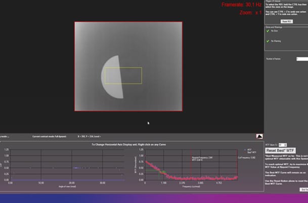
A cross target or knife-edge target is accurately projected, and the objective of the NVD is adjusted to sharpen the image. This test is performed either using the familiar method of visual inspection or through precise MTF curve calculation and optimization.
In this case, HGH’s exclusive high-resolution Eye-Camera replaces the human eye behind the eyepiece.
Combined with a dioptometer accessory, this configuration allows for measurement of the zero position and diopter adjustment range.
Measurement of the spatial resolution
The spatial resolution is evaluated through the observation of accurate USAF1951 target patterns under different night levels simulated through the fine adjustment of the ISV210-F luminance and combined with neutral density filters.
Goggle Axis Alignment
The measurement and the adjustment of the parallelism of left and right goggle axes is a critical parameter for the comfort of the operators.
Automated Axis Alignment Method
HGH developed an automated method for measuring this parameter using the Eye-Camera, which observes the left and right images of a projected hole target. The system compares the positions of the two images to determine alignment.
For more information, please refer to the paper.
Prism-Based Visual Alignment Method
The method using a prism-based optical system at the output of the eyepiece, combining the left and right images is also available. This method used a rectangle target and is very familiar to many operators.
Gain Measurement and Spot Defect Detection
Dedicated testing conditions
Facing directly toward the output aperture of the ISV210-F visible and NIR source, the entire field of view of the NVD receives a uniform low-light irradiance. This enables accurate gain measurement and automated spot defect detection.
Gain calculation using luminancemeter
Using a calibrated luminancemeter, the gain is measured as the ratio between the luminance of the intensified image measured at the output of the eyepiece and the irradiance received by the NVD.
Automated spot defect detection and location
Spot defects in I² tubes have traditionally been detected through visual observation, including counting and estimating the size of defects within circles defining the central, middle, and outer fields of view.
This visual method is prone to human error. HGH has developed an automated detection method based on uniform image acquisition of the I² tube using the Eye-Camera, combined with an algorithm that:
- Detects and counts each spot
- Measures the size of each defect
- Lists the output results in compliance with MIL standards
For more information about this method, read the paper.
Ready to optimize your electro-optical maintenance operations?
Looking to improve your thermographic camera calibration setup? Need a blackbody system adapted to your production line or research lab ?

References
