Industrial Thermography - FAQ

How to measure kiln shell temperature in shadow areas?

FAQ

Kilnscan infrared scanners are non-contact thermal monitoring systems, which are designed to provide a complete temperature map of the outer shell of a kiln, by collecting the infrared radiation over a wide field of view (FOV).

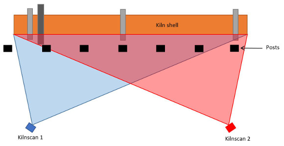
Referring to the illustration below: the FOV is symbolized by a light blue triangle, with Kilnscan scanner at the outside vertex. To measure the temperatures over the full length of the kiln shell, Kilnscan can scan over angles from 90° up to 140°.

Shadow areas on kiln shell thermal map

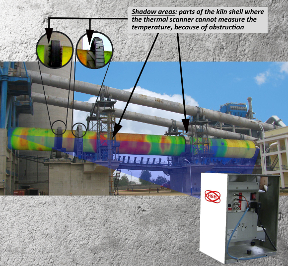
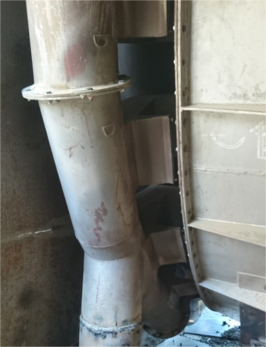
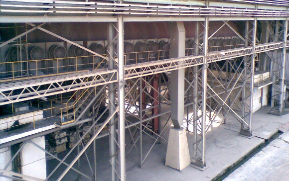
Some obstacles, such as buildings, posts and pillars may often mask parts of the shell. Besides, as shown in the zoom thumbnails in the above picture, tyres and drive wheel seen through at some angle from the scanner also create measurement blind zones in their immediate vicinity. Overall, these masked zones are the “shadow areas”.

Rotary kiln with a few small-size obstructions

In order to monitor the temperature over the full length of the kiln shell, with no dead zone, several thermal spot sensors, called shadow pyrometers, are installed in front of the shadow areas, close to the shell. They are connected to the KILNSCAN receiver unit which operates as a data hub and merges temperature information from all sensors, to display the complete, seamless thermal map of the kiln shell.

Up to 8 shadow pyrometers can be connected to KILNSCAN receiver unit. Each pyrometer can be aligned in front of the kiln to monitor a spot equivalent to the size of a single refractory brick in shadowed or concealed areas.

Shadow pyrometers are particularly convenient in complex access areas, as illustrated in the picture below, where a cooling air tube is masking a wide part of the shell to the thermal scanner. Only the addition of a shadow pyrometer enables to monitor hot spots behind the tube.

Cooling air tube in front of the kiln shell

Rotary kilns with many obstructions or large-size masked areas

The picture below was taken during the commissioning of Kilnscan scanners for Tasek in Malaysia. In this typical complex configuration, the line of sight of each scanner was obstructed by several posts and pillars. In comparable configurations, the best recommended thermal monitoring solution involves 2 or 3 scanner heads.

At Tasek cement plant, 3 KILNSCAN scanners, each with a field of view of 140 °, were installed in order to display a thermal map with no dead zone. In such specific cases, wide-angle scanners are aligned with an overlap in their line of sights. The thermal image is then reconstructed by combining the data from these two or three scanners, eliminating shadows for a perfect full monitoring of the shell.

Tasek cement plant: 3 kilnscan thermal scanners installed for a complete temperature map without blind zones
Configuration installation scanners thermiques
2 thermal scanners configuration, with FOV overlapping

Need more information ?