A blackbody is an object which absorbs all incident radiations it receives whatever the wavelength or direction and re-emits all these absorbed radiations. An important property of blackbodies is that the re-emitted energy level only depends on the temperature of the blackbody.
For a prescribed temperature and wavelength, no surface can emit more energy than a blackbody.
A blackbody is then an optical reference source, though a theoretical device.
The infrared radiation is the electromagnetic radiation where wavelengths are between 700 nanometres and 1 millimetre. Thus, it is located between the red limit of visible spectrum and the shortest microwaves.
However, taking into account the major applications of thermal sensors, the main considered spectral range is between 1 µm and 50 µm including 3 major sub spectral ranges corresponding to the atmosphere transmission windows:
Usual objects are not blackbodies. They do not absorb 100% of the incident energy and usually select the absorbed wavelengths.

Consequently, they cannot re-emit all the incident energy. The ratio between the re-emitted energy of a usual object and the re-emitted energy of a blackbody at the same temperature of the object is called emissivity and noted ε. This ratio depends on wavelength and is comprised between 0 and 1. Of course, the emissivity of a true blackbody equals 1.
However, such bodies do not exist and manufacturing “blackbodies” consists in creating optical sources with emissivity value as high and as constant as possible over the widest spectral range. These sources are called grey bodies but practically sources with emissivity higher than 0.9 are also called blackbodies.
As mentioned in FAQ section, the quantity of energy emitted by a true blackbody only depends on its temperature. This radiation level, named Radiant Emittance R, is defined by the following distribution discovered in 1900 by the German scientist, Max Planck:
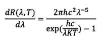
Where:
No need for you to learn the Planck’s law by heart!
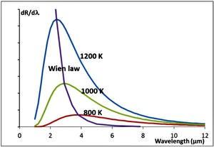
However it is good to know some important properties of blackbodies as consequences of the Planck’s law:
![]()
Example: a blackbody at 800K (i.e. 527°C approx.) emits its maximum radiation at about 3.6 µm, i.e. in the MWIR spectral range.
As the radiation level of a blackbody only depends on its temperature and is well-known through the Planck’s law, blackbodies are used as optical reference sources for optical sensors. Practically, as the temperatures values for blackbodies emitting over the visible range are very high and as, consequently, this leads to very expensive sources compared to classical lamps, the blackbodies are mainly used over the infrared spectral range starting from 1 µm. That’s why blackbodies are also known as Infrared Reference Sources.
The main applications are of course IR sensors calibration and their specifications measurement.
Depending on the applications and on the IR sensor range of sensitivity, the manufactured blackbodies are divided into 3 families usually defined by their temperature range:
A blackbody is usually made of two parts linked through a cable:
The infrared radiation is the electromagnetic radiation where wavelengths are between 700 nanometres and 1 millimetre. Thus, it is located between the red limit of visible spectrum and the shortest microwaves.
However, taking into account the major applications of thermal sensors, the main considered spectral range is between 1 µm and 50 µm including 3 major sub spectral ranges corresponding to the atmosphere transmission windows:
An IR camera is sometimes sensitive to the temperature difference between an object and its background. Consequently, some tests require to simulate an object and its background and to have a simultaneous and accurate measurement of both.
The simulation of an object and its background is made by placing a target in front of the emissive surface of a blackbody.
An infrared target is a thin sheet coated with high emissivity coating with stuck patterns. The object is made by the blackbody seen through the holes and the background is the solid part of the sheet.
Consequently the temperature of the object is the temperature of the blackbody while the temperature of the background is measured by inserting a temperature sensor into the mount of the target.
As some IR cameras specifications depends on the temperature difference between an object and its background, it is necessary to have the object temperature adjusted with respect to the background temperature. A differential blackbody allows this function by adjusting the temperature of the object in real time to a fixed temperature difference (positive or negative) with respect to the floating temperature of the background.
The tests which can be performed on an IR camera using a blackbody can be divided into 4 categories:
HGH offers an efficient solution to the test of IR Cameras through the INFRATEST software
The following table is a suggestion of the recommended targets for the usual tests:
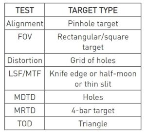
Noise tests usually do not require any target.
The NETD (Noise Equivalent Temperature Difference) is the temperature difference between an object and its environment required to generate a variation of the IR camera signal equal to its temporal noise, i.e. its 1-sigma temporal instability. It can be considered as the thermal resolution of an IR camera.
The MTF (Modulation Transfer Function) curve shows the contrast value (between 0 and 1) of a sinusoidal image focused on a camera as a function of the frequency of the image. It gives information about the spatial response of the camera. This curve is usually obtained by the Fourier transform of the Line Spread Function, i.e. the signal response of the cameras to an extremely thin slot.
The MRTD (Minimum Resolvable Temperature Difference) is a standard performance measurement for Thermal Imagers. This measurement leads to the determination of the DRI ranges (Detection, Recognition, Identification ranges) of the infrared camera under test.
The MRTD measurement is performed using:
The differential blackbody enables to set a positive or negative temperature difference between the target bars and their background (the emissive surface of the blackbody). The MRTD curve is plotted by determining the minimum temperature difference between the target and the background, required to distinguish the 4 bars on the thermal image of the camera, as a function of the spatial frequency of the 4-bar target.
To perform a fast and accurate MRTD test, patterns of 4-bar targets, with optimized spatial frequencies, can be computed depending on the Field of View and the resolution of the camera, and on the focal length of the collimator. Download our calculation sheet to determine the target pattern suiting your needs.
For more information, do not hesitate to contact our specialists.
Luminous parameter:
Luminance is a quantity representing the brightness of sources independently from its size and its emitting cone. This value is consequently often used to compare tow sources.
The USI unit of luminous flux is Lumen, abbreviation lm.
1 lumen = 1/683 Watt at 555 nm
555 nm is the wavelength to which the eye is the most sensitive.
The USI unit of luminous intensity is Candela, abbreviation cd.
1 cd = 1 lm/sr
1sr = 1 steradian is the cone of light spreading out from the source which would illuminate 1 m² at 1 m distance from the source.
The USI unit of luminance or Radiance is Candela per square meter, abbreviation cd/m².
The USI unit of illuminance or irradiance is Lux, abbreviation lx.
1 lux = 1 lm/m²
Other units are available: