

INFRATEST SOFTWAREPRECISION AND VERSATILITY FOR EO DEVICE TESTING
INFRATEST Software offers exceptional precision and versatility for the testing and qualification of electro-optical devices. It is particularly efficient for cameras, thermal imagers, Night Vision Devices and binoculars, goggles, and other sensors, ensuring optimal performance and accuracy.
SUPPORTED DEVICES
INFRATEST Software supports a wide range of devices and electro-optical systems:
THERMAL CAMERAS (COOLED OR UNCOOLED)
NETD, spatial resolution (LSF/MTF), MRTD and DRI ranges, alignment of OPTICAL AXIS VS MECHANICAL AXIS
VISIBLE TO SWIR CAMERAS
Noise equivalent Irradiance, effective focal length, resolution (MRC), distortion, field of view, latency
NIGHT VISION GUN SIGHTS & GOGGLES
Gain, resolution, infinity focus, zero and range of eyepiece, parallelism of goggles axes, figure of merit, spot defect
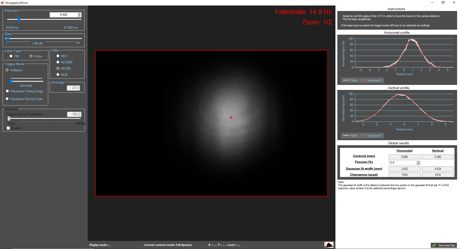
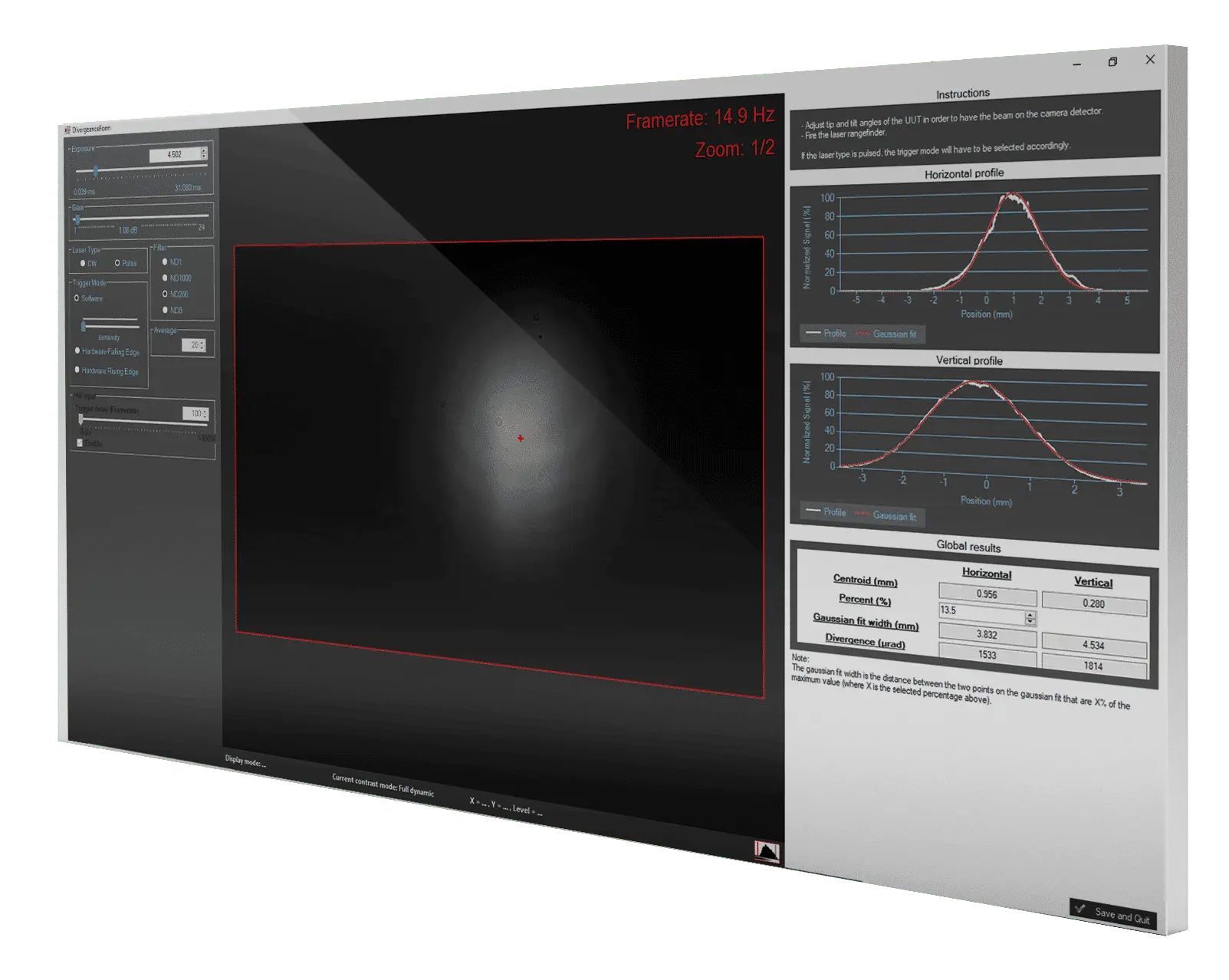
LASER RANGEFINDERS AND DESIGNATORS
Alignment, beam profiling, divergence, accuracy of distance measurement, laser pulse energy and power
MULTIPLE AXES OPTRONIC SYSTEMS
Camera axis alignment, boresighting between cameras (any type) and mechanical axis
MULTI-FUNCTIONAL BINOCULAR SYSTEMS
Alignment of axes, large apertures compatible
FOCAL PLANE ARRAYS AND CAMERAS
Bad pixel location, non-uniformity correction, temporal noise and fixed pattern noise measurement, detectivity, responsivity
Civil & Military Applications
INFRATEST Software is particularly appreciated for the following applications:
- R&D: Product development, optimization and qualification
- Production line: Quality control
- Maintenance: Proper operation check, operational condition maintenance
MAIN ADVANTAGES
HIGH ACCURACY
MODULAR
VERSATILE
Test Bench & Related Tools for Automatic Control
- Blackbody Temperature
- Visible Source Luminance
- SWIR source radiance
- Target pattern
- Azimuth, Elevation Adjustment,
- Motorized Stages Position
Video Signal Management
- Real-time Acquisition
- Live Display
- Image Acquisition
- Accurate Measurement Analysis
- Full Performances Calculation
- Auto-saved Data
- Multi-format Data Export (.csv, .xml, .png, .html)
Video Protocols
INFRATEST Software is compatible with a wide range of video protocols, including:
- Analog (CCIR, RS170, PAL, NTSC)
- Camera Link
- USB3 Vision
- 3G SDI, HD SDI, SD SDI
- GigE Vision
- DVI, HDMI
Custom Scenario for testing electro-optical systems
The flexible structure of INFRATEST oftware allows the operator to build customized test scenarios for any electro-optical system. The operator can pick from an exhaustive list of hardware control functions and accurate tests, then create sequences with the “drag & drop” function. This user-friendly interface enables the creation of fully automated test benches based on HGH products, saving time and offering unlimited testing capabilities.
Contact us to learn more about our INFRATEST Packs:
![]() INFRATEST Camera Pack – Includes the essential functions to test any kind of cameras from visible to Infrared.
INFRATEST Camera Pack – Includes the essential functions to test any kind of cameras from visible to Infrared.
![]() INFRATEST Camera Expert Pack – Includes advanced test functions, such as accurate measurement of the Distorsion or range calculation based on TOD method, in addition to the Camera Pack functions.
INFRATEST Camera Expert Pack – Includes advanced test functions, such as accurate measurement of the Distorsion or range calculation based on TOD method, in addition to the Camera Pack functions.
![]() INFRATEST Night Vision Pack – Offers objective and accurate measurements of NVD, including the challenging measurement of the parallelism of goggle axes.
INFRATEST Night Vision Pack – Offers objective and accurate measurements of NVD, including the challenging measurement of the parallelism of goggle axes.
![]() INFRATEST Laser Pack – Includes Laser Ragefinder and Laser Pointer test functions, including 2 methods for laser alignment with VIS or IR axis.
INFRATEST Laser Pack – Includes Laser Ragefinder and Laser Pointer test functions, including 2 methods for laser alignment with VIS or IR axis.

References
