![]() Infratest Plateform
Infratest Plateform
Infratest平台是测试集的基础。它可以远程快速驱动任意测试工具。一键设置黑体或积分球光源的温度。也可以在准直仪的焦点上定位目标,选择被测广电系统的方位角/俯仰角等。 控制面板可以实时显示测试工具的状态,也能够显示相机视频信号,同时具有图像存储功能。
Infratest Platform 离不开HGH提供的硬件系统,两者搭配使用: 黑体,积分球光源, IRCOL测试平台, OPAL 系统等。
![]() Infratest 相机测试包
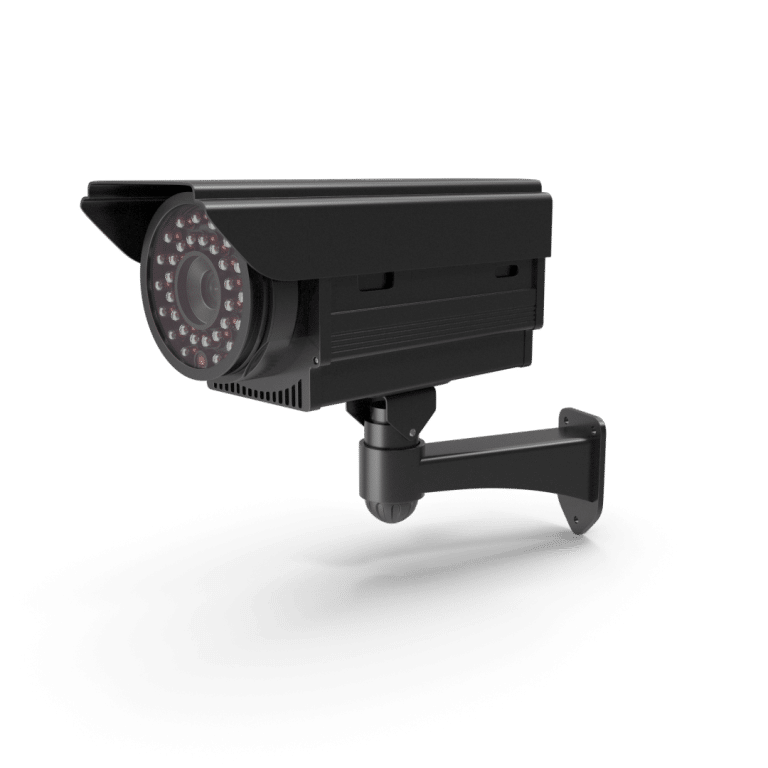
Infratest 相机测试包
Infratest Camera Pack 是针对不同配置和视频协议类型相机测试的理想解决方案,适用于可见光,近红外,红外以及微光相机等。
无论制冷或非制冷热相机, Infratest Camera Pack都能保证测试参数的精确 性。毫无疑问,对于研发中心研发中或生产线上的相机测试来说 Infratest Camera Pack都是最好的应用解决方案。
![]() Infratest 激光测试包
Infratest 激光测试包
激光测距仪和激光指示器的测试是一项艰巨的挑战,因为它既涉及到各种波长的激光光束,也涉及到各种波长的光轴。 Infratest Laser Pack可以很好地应对此挑战并完成任务。
包括眼睛安全类型的激光器在内的所有激光器类型都可以用此测试包的测试方法。此包特别包含激光发射对准测量的两种方法:瞄准轴法、可见光和红外法。
![]() Infratest 夜视镜测试包
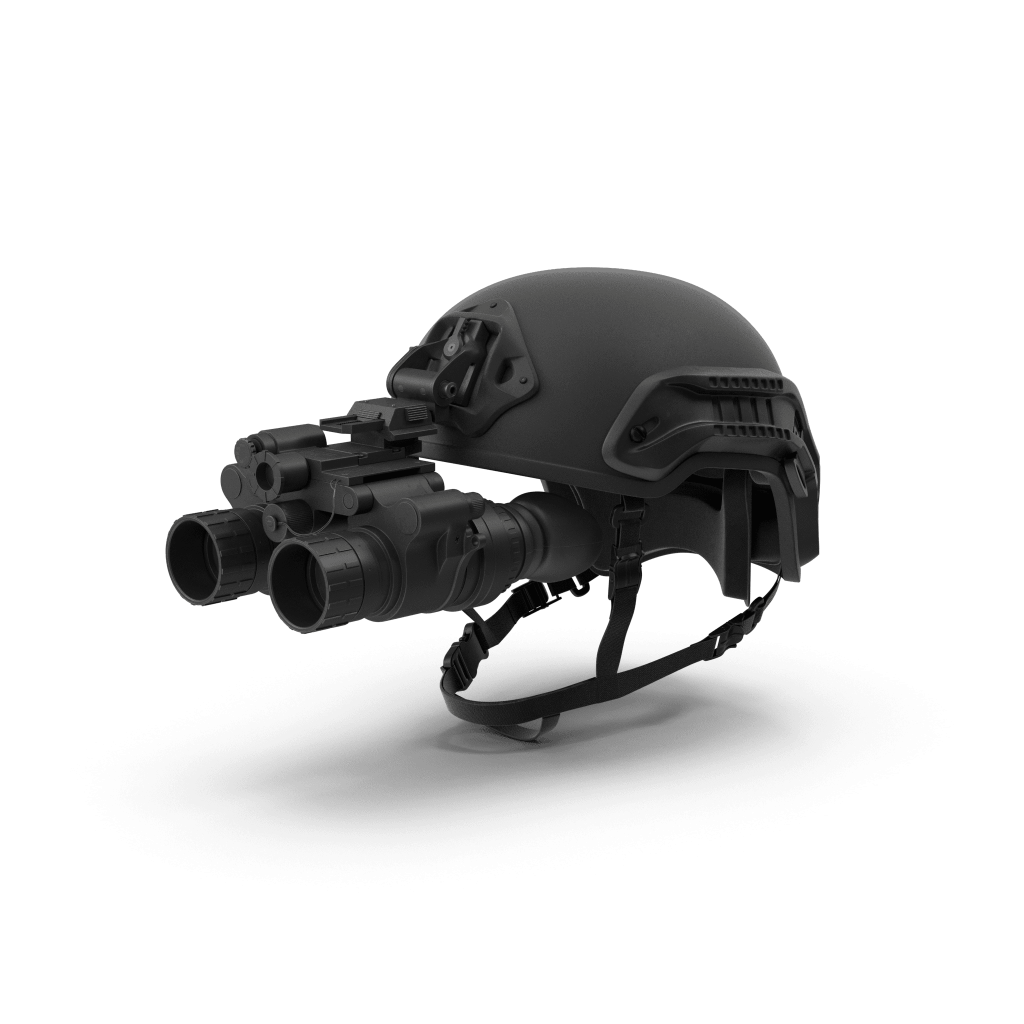
Infratest 夜视镜测试包
Night Vision Pack 专门用于夜视设备的测试。独特的眼镜相机镜头具有高分辨率,同时能够消除目镜后人类眼睛的主观性。因此, Infratest Night Vision Pack 能够实现对夜视设备主要参数客观且精确的测量。
尤其适用于设备维护, Infratest Night Vision Pack 能够区分有缺陷的和可操作的夜视设备。
![]() Infratest Camera Expert Pack
Infratest Camera Expert Pack
Infratest Camera Expert Pack 致力于满足那些追求合格的高性能相机的要求客户。同时也可哟应对复杂参数的测量。Camera Expert Pack 还能够提供一些高级功能,如精确测量扭曲图,即使是鱼眼相机,或基于客观TOD方法的距离计算
![]() Infratest Camera Expert Upgrade
Infratest Camera Expert Upgrade
Want to go further in the test of your cameras? Have your Infratest Camera Pack upgraded with the Camera Expert Upgrade.
 Infratest Platform
Infratest Platform is the basement of the INFRATEST suite. It allows to quickly and remotely drive any testing tool. In an eyeblink, you can select the temperature of several blackbodies or ISV sources, locate a target at the focus of a collimator, select the azimuth/ elevation position of the tested Electro-optical system… Each testing tool status is displayed in real time through the dashboard. Infratest Platform also displays the video signal of your camera in real time and offers image saving capabilities.
Infratest Platform is supplied with any HGH hardware system: blackbodies, ISV sources, IRCOL bench, OPAL system, etc. Try it now! 
Infratest Camera Pack
Infratest Camera package is the ideal solution for testing your camera whatever its configuration and its video protocol. It is suitable for visible, NIR, low light and SWIR cameras.
Infratest Camera Pack ensures the accurate measurement of all main parameters of thermal imagers, using cooled or uncooled detectors. Whether you are developing a new model of camera or responsible of production line, Infratest Camera Pack is the best solution for your application. Infratest Laser Pack
Testing Laser Rangefinders and Laser Pointers is a challenging task as it deals with both laser beams and optical axes of various wavelengths. This challenge is achieved through the Infratest Laser package.
Infratest Laser Pack testing methods are compatible with all laser types including eye-safe. The Pack particularly includes 2 methods for laser transmitter alignment measurement with sighting axis, visible and infrared.
Infratest Night Vision Pack
Night Vision Pack is a dedicated to testing any night vision device. Combined with HGH’s exclusive high-resolution Eye-Camera replacing the subjective human eye behind the eyepiece, Infratest Night Vision Pack offers objective and accurate measurements of the main parameters of your NVD.
Particularly adapted for maintenance application, Infratest Night Vision Pack allows you to sort out between defective and operative NVDs.
Infratest Camera Expert Pack
Infratest Camera Expert Pack is dedicated to demanding operators seeking for qualifying high performance cameras and measuring complex parameters, the Camera Expert Pack offers the most advanced functions such as the accurate measurement of the Distortion map even for fish-eyed cameras or the range calculation based on the objective TOD method.
 Infratest Camera Expert Upgrade
Want to go further in the test of your cameras? Have your Infratest Camera Pack upgraded with the Camera Expert Upgrade.